Modular coil gun revisited
Back in 2012, I designed and 3D printed a desktop modular coil gun. I made a video of the build at the time and published it on YouTube, so I could share it with friends. The coil gun ended up on my shelf and I moved on to the next project.
Looking back, I see that this particular video has gotten quite a few views since then. I have received a few requests for design details since then, many of which I haven’t responded to yet (I guess 9 years latency is pushing it a bit, but hey, I’ve been busy!)
This weekend I decided to dig through some of my old notebooks from the period to see if I could find anything that resembled any form of documentation. The excavation trigger was a recent request via YouTube from someone who wanted to reproduce the project (Hi, Maximiliano! :)).
Since this was a rather ad-hoc build, I only produced a few handwritten schematics. I also did a few LCR simulations, from which I have kept the printouts. The 3D models of the physical structure were done in a non-cloud predecessor of Fusion 360. These files are unfortunately long gone, but I’m guessing that most people are most interested in the schematic anyway.
Trigger circuit⌗
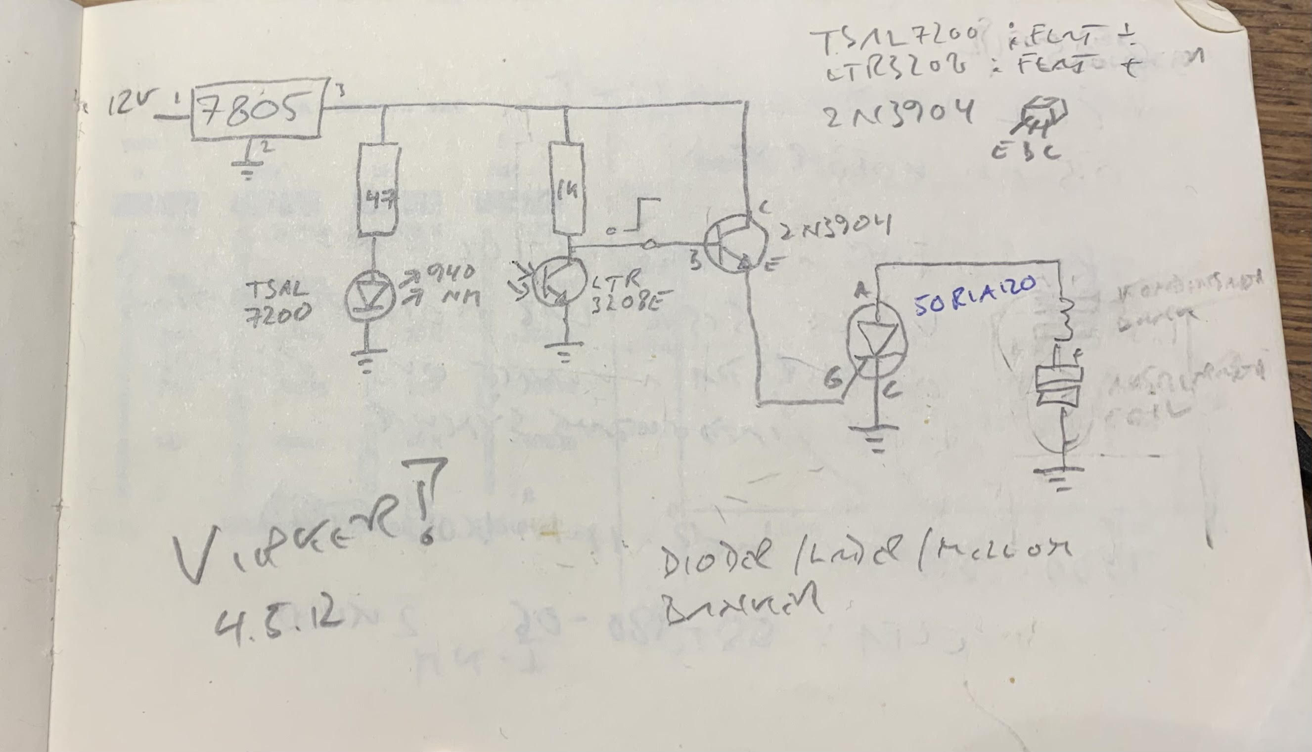
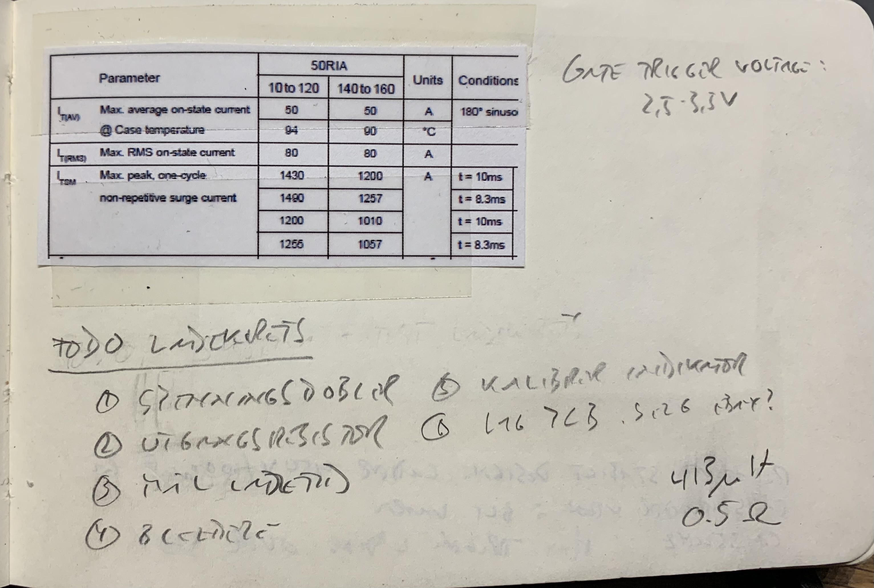
As you can see, the trigger circuit is pretty simple. The gun “barrel” was made of a carbon fiber tube. This tube had tiny holes drilled into the sides, where an infrared TSAL7200 LED was placed on one side and an LTR3208E phototransistor sat on the other side. When the light beam was interrupted by the projectile moving through the tube, this turned a 2N3904 small signal transistor on. This in turn triggered a 50RIA120 SCR. This SCR then shorts the capacitor bank through the acceleration coil.
Each module is fitted with a dedicated capacitor bank, consisting of 6 450V/1000uF photoflash capacitors wired in parallel.
Note: When working with capacitors like these, you should always assume that they are storing a lethal charge. Never assume that they are fully discharged after firing, and never, ever try to discharge a capacitor bank with something like a screwdriver. This will result in an extremely loud bang - accompanied by a spray of vaporized screwdriver. Most likely in an unfortunate direction.
Note: Always mount bleeder resistors across the terminals of each capacitor. This will ensure safe discharging of the bank in a relatively short time. (Bleeder resistors are not shown in the schematic)
The coils are all hand-wound on 3D printed bobbins, using enameled copper wire. I don’t recall the exact wire dimensions, but it was most likely somewhere between 0.5 and 1 mm in diameter.
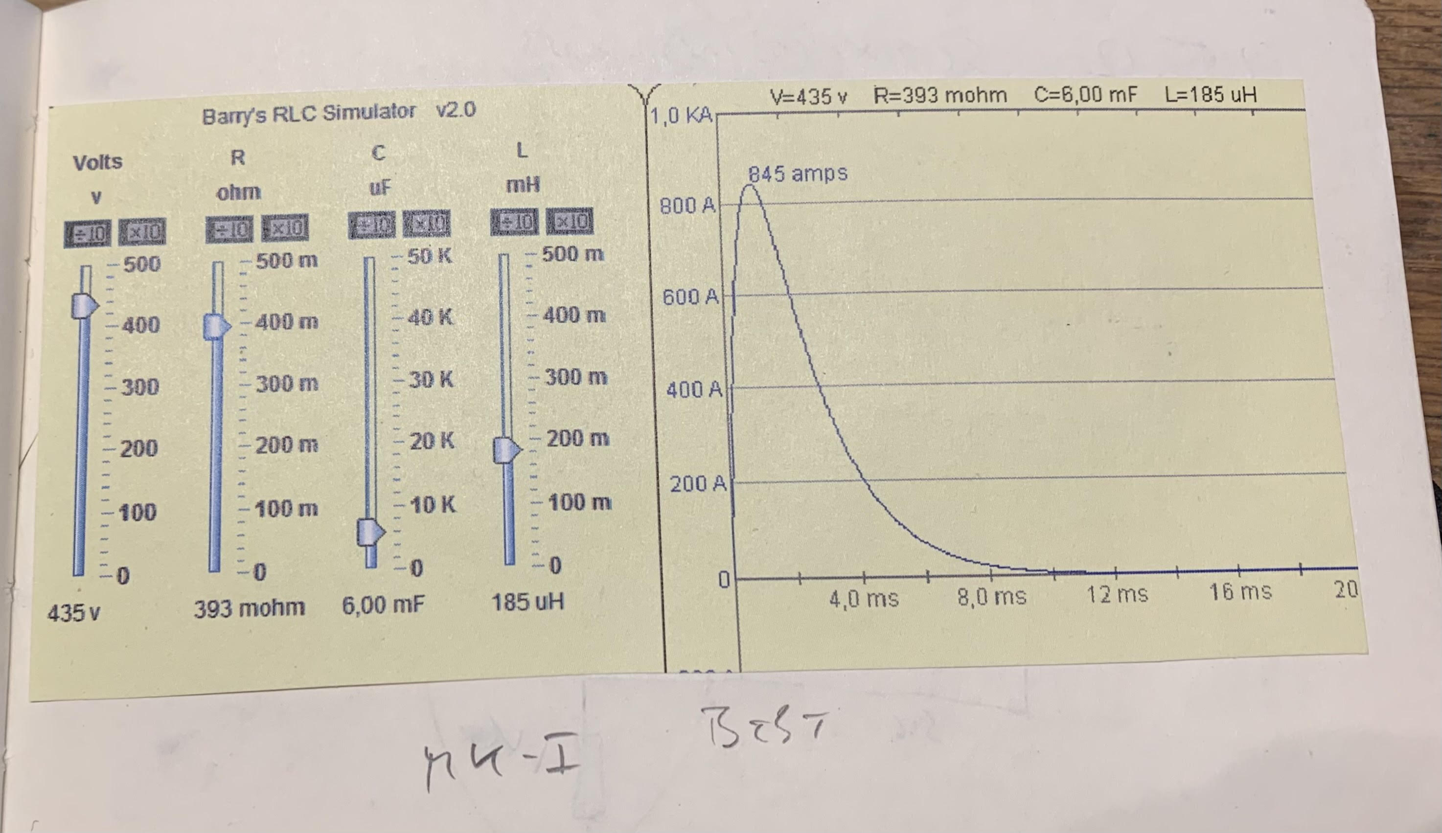
When the SCR is triggered, it basically short circuits the capacitor bank through the accelerator coil. This circuit will have negligible resistance and the coil has very low inductance. This produces a current pulse of hundreds of amps. The SCR has only an 80A current rating, but it will still survive non-repetitive pulses of 1200A as long as you keep the pulse short enough.
Simulation⌗
Together, the capacitor, acceleration coil, and wires in each module make up an LCR circuit. An LCR circuit is an oscillating circuit. The challenge here is to design an LCR circuit where the inductance, capacitance, and resistance will result in a fast ( == a few milliseconds) and fully dampened pulse and not an oscillating pulse train.
An LCR meter is almost a must when designing a circuit like this since the inductance of the hand-wound coils will have to be measured. The same goes for the DC resistance of the circuit.
Charging circuit⌗
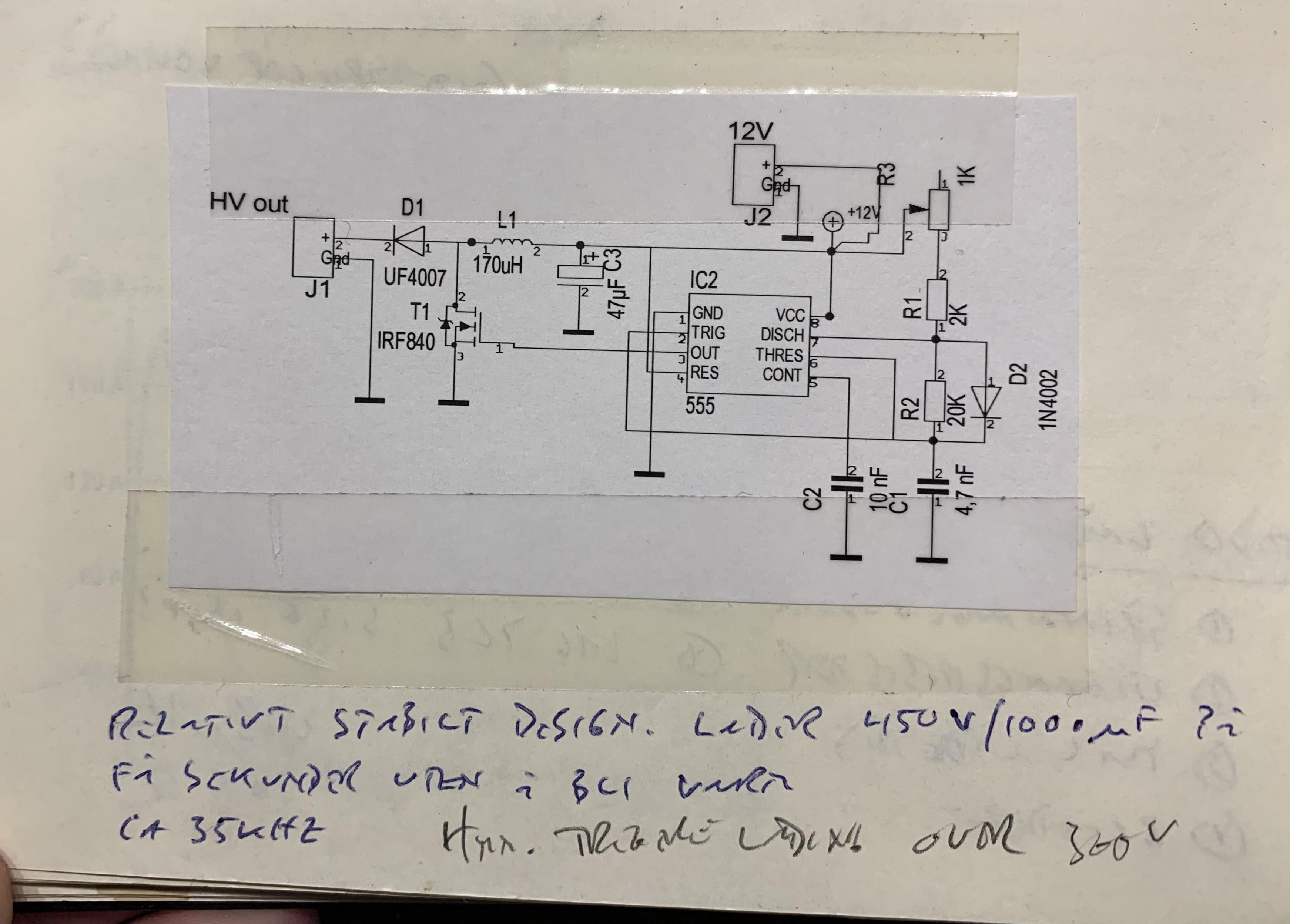
In the design, I re-used a 555 based boost converter design that I had borrowed somewhere on the internet. This worked, but it wasn’t particularly efficient. Charging the bank above 50% was extremely slow.
If I were to redesign this today, I would most likely design the charger around one of the specialized commercially available photoflash charger ICs instead.
Charge level indicator⌗
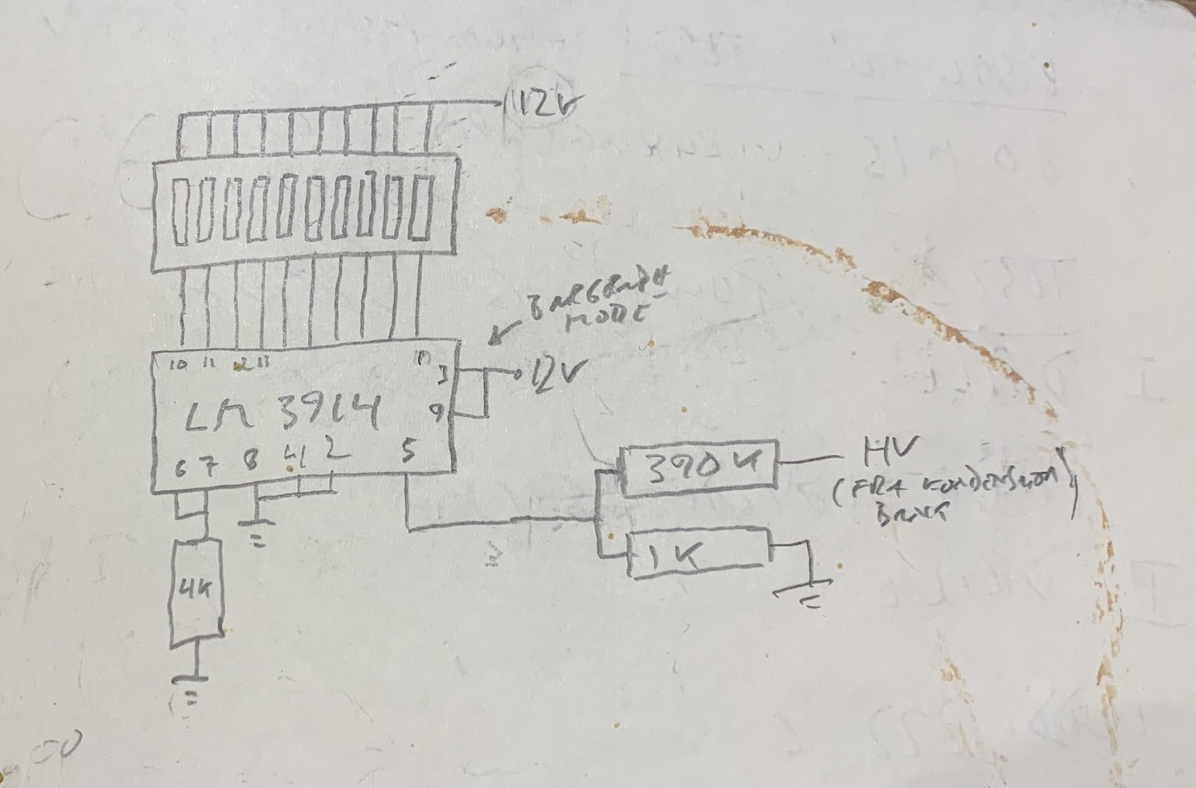
The charge level indicator is just a 10 segment LED bar graph hooked up to an LM3914 and a voltage divider.
Notes on modularity⌗
I thought it would be fun to make the design modular at the time. There is, however, one aspect of this modularity that hasn’t been addressed in this design, and that is timing.
Since the projectile will travel at a different speed exiting the module than when it was when entering the module, the placement of the optical trigger matters.
Note: If the coil triggers too early, the projectile wouldn’t get an acceleration boost, and if the coil triggers too late, it could slow the projectile down.
If I were to redesign this today, I would place the trigger directly at the module entrance and then feed the trigger output into a microcontroller. The microcontroller would then start executing a programmable timer when the projectile entered the barrel and trigger the SCR when the timer finished. The timer would have to be configured individually for each module added and the optimal delay for each module would have to be decided by trial and error while measuring exit velocity.
In case you want to build your own⌗
- Don’t get your hopes up regarding achievable muzzle velocities with DIY coil launchers.
- Do your own research. IEEE Xplore has tons of papers on electromagnetic launchers and coil guns.
- Working with high voltages and capacitor banks is inherently dangerous, even if you know what you are doing.
- Please be careful if decide to embark on a project like this. And if you aren’t comfortable working with high voltage / high energy stuff - don’t even consider it. This launcher has the size of a desktop toy, but it stores enough energy to kill you.